PCB WIZARDS.COM


Last update:

10/29/2007

  Glossary R
Site Map Location FAQ
  

Glossary A
Glossary B
Glossary C
Glossary D
Glossary E
Glossary F
Glossary G
Glossary H
Glossary I
Glossary J
Glossary K
Glossary L
Glossary M
Glossary N
Glossary O
Glossary P
Glossary Q
Glossary R
Glossary S
Glossary T
Glossary U
Glossary V
Glossary W
Glossary X
Glossary Y
Glossary Z


Glossary of Terms

R


Reference Designation - Reference Designations are letter and number codes assigned to items that are part of an assembly. This 'shorthand' code allows components in a printed circuit board to be found easily while working on a board assembly or locating them and their complete descriptions in a Bill of Material or parts list.


Standard Reference Designations for Electrical Equipment can be found published in ANSI Y32.2 1975/IEEE STD 315. Below is a partial list of the reference designations used in electronics.

A    Assembly

AR  Amplifier

AT  Attenuator; Isolator

B    Blower, Motor

BR  Bridge Rectifier

BT  Battery

C    Capacitor

CB  Circuit Breaker

CP  Coupler

CR  Crystal Rectifier (Diode)

D    Diode; Thyristor; Varacter

DC  Directional Coupler

DP  Diplexer

DL  Delay Line

DS  Display; LED Lamp

E    Terminal

F    Fuse

FB  Ferrite Bead

FD  Fiducial

FL  Filter

G   Generator, Oscillator

HW Hardware

HY  Circulator

J    Jack Connector (Least Movable)

JP  Programming Jumper


K      Relay
L      Coil; Inductor

LS    Loud Speaker/Buzzer

M      Measuring equipment, Meter

MH    Mounting Hole

MK    Microphone

P      Plug Type Connector (Most Moveable)

PS    Power Supply

Q      Transistor

R      Resistor, or Potentiometer

RN    Resistor Network

RT    Thermistor

S      Switch

T      Transformer

TB    Terminal Block

TC    Thermocouple

TP    Test Point

U      Integrated Circuit or inseparable assembly

V      Electron Tube, Photoelectric Cell

VR    Voltage Regulator

W     Cable Transmission or Wire Jumper or Busbar

X      Socket

Y      Crystal, Oscillator


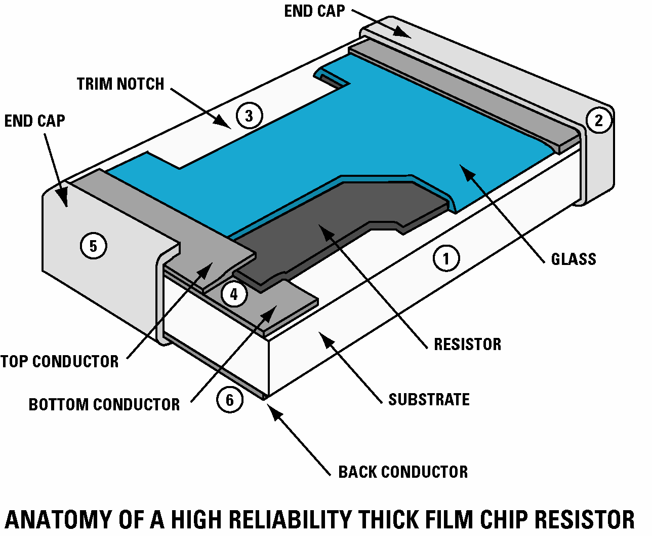
Resistance - That property of a material that impedes the flow of electrical current, reduces voltage and dissipates power in the form of heat in an electrical circuit. The unit of measurement for resistance is the OHM which is defined as the resistance required to maintain an electrical current of one AMP at One Volt.


1 OHM = 1AMP @ 1VOLT


The electrical symbol for resistance is the  or the Greek Letter 'Omega'.


Resistor- The Reference designator for the resistor per ANSI Y32.2 is R

One Thousand Ohms is abbreviated with K as in Kilo-Ohms (10K = 10,000 ohms)

One Million Ohms is abbreviated with M as in Meg-Ohms (100M = 100,000,000 ohms)

Resistors are available in Axial, Radial, Power D-PACK or TO-220, SIP arrays, SMT Chip packages and thick film embedded resistors that are screened or imaged into a printed circuit.  Axial leaded carbon composition resistors come in 1/10W, 1/8W,1/4W, 1/2W, 1W, 2W 5W, 10W sizes... sized for the watts of power they can dissipate without being destroyed by the heat they generate.


Some sources for resistors would be Bourns, Dale, SRT, Rohm, Caddock... there are many.


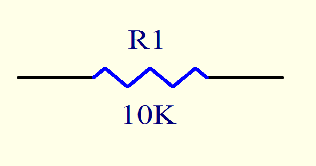
Resistor Schematic Symbol


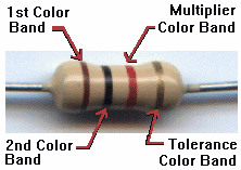
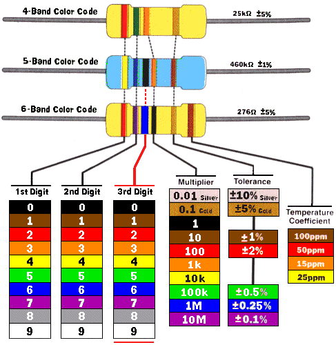
Resistor Color Code - A code for determining the value in Ohms of an axial leaded resistor.

See the Graphical Resistance Calculator - http://www.dannyg.com/examples/res2/resistor.htm


Black    = 0

Brown   = 1

Red      = 2

Orange = 3

Yellow  = 4

Green   = 5

Blue     = 6

Violet   = 7

Gray     = 8

White   = 9


None   = 20% Tolerance

Silver   = 10% Tolerance

Gold    = 5% Tolerance


RG cable -  or coax as we know it, was developed by Bell Laboratories during WWII.  Aircraft radio systems that required long-wire antennas, like for example long range bombers, needed a method to route the signal to either the belly or tail mounted long-wire reels without radiating within the fuselage.  Bell Labs developed it and called this new cable Radio Guide or "RG".



Hit Counter

Copyright © 2004 - 2007 PCB Wizards.COM
 Back Home Up Next